Saturday, April 5, 2014

REHABILITATING AN OLD LAMP


I've been going through all my miniatures and tossing some, giving away some, selling, and categorizing others into boxes and drawers.

The thing I've liked best about this process is finding things I long ago acquired that are either broken or no longer work.

One category is old lamps. I haven't taken any photos because I'm never sure whether I'll successfully rehab an old lighting fixture into a new LED fixture.

I found a lamp in an envelope that was broken apart but still had all its pieces including a 12v bulb. It was hand painted with tiny flowers all over the two largest parts. The trouble was that the only good parts to the lamp were those two hand-painted parts.

The base was broken so the lamp would not stand up. The plastic part that held the glass chimney and the top part of the lamp was cracked and discolored.

I began by using a blow dryer to work all the glue off of these beads and take the broken plastic parts off of the painted beads. When I had the two hand-painted parts separated, I saw that the hole through the base part (large bead) was too small to either get the old wire out or get an LED wire through it.

<sigh> Not knowing for sure that this was a plastic bead but suspecting it was, I got my small drill out and carefully drilled out one end. (Yes guys, I wore eye protection and gloves) When it did not shatter, I knew it was plastic, so I enlarged the holes at both ends. I got the old wire out of that bead. I continued to enlarge the holes little by little until I could fit a small hollow brass rod through.

Next I needed jewelry findings which would mimic the broken and discolored plastic parts. I tried Judith (JAR-JAF) but what I really needed was her whole selection, so I could sit down and try one piece after another until I found the pieces I needed. Since she lives all the way across the US from me, this was not practical.

Then, fortuitously, I got sent to a town with a large hospital to have a little proceedure done. Having to stay close to the hospital for 3 days but not being in the hospital, I had time to roam the city. I found a lovely bead store.

I had taken all the parts of the lamp with me plus a chip LED and a coin battery. I spent an entire afternoon plowing through the things the store had that could complete the lamp, found what might work and came home with several choices, plus (and who woulda guessed?) more beads. (I am sooo not in control of myself, LOL.)

Anyway, this morning I got going and put the lamp together, and it is wonderful. I've slipped the chip LED into the setup and attached it to a coin battery. As you can see, a chip LED gives off loads of lumins. Too bad I did not take pics from the beginning. 

However, now that I have all the parts stacked and ready to glue, I've taken these two photos.


I know. It looks a bit wonky, but hopefully I'll get it verticle when it's glued.

Tuesday, July 9, 2013

Part 7 Constructing Light Fixtures: Workbench Fixture


Creating a Shop Light to hang over the workbench has not been easy.

This is quite a process. I initially thought to make a fixture that would curve over half circle ends and, using a heavy piece of paper with a metalic coating, I made a prototype. I glued the pieces together and they fit nicely, but as soon as I let go of the structure, the curved part of the shade was so strong in its need to pop back into a flat position, that it tore itself from the glued ends.


New design:


I began on PhotoShop making a pattern for the long light that would have flat planes folded so they would gradually slant. This worked great when I made up a prototype in printer paper.(see above) 

Next, I made a shade from a piece of scrap-booking card stock. The same card stock I had used before with one shiny metallic side and one plain paper side.

I chose to have the shiny side on the inside of the fixture as I wanted to reflect as much light as possible down on my workbench.

The pattern is a bit over 3” long by 2 – 3/4” high. The ends look like uneven half hexagons.

The dark line across the center of the rectangle is the top center of the lamp.

The plan was to gently fold on each horizontal line to create a shape that would fit the ends (bottom two   pattern pieces).

I made the card stock fixture and it seemed to work pretty well.


So I transferred the pattern to some very thin metal. Now, I began to have problems. The aluminum was not rigid enough. As I would put a bend in one section, the next part of the shade would warp. Hummm... I really needed a bit heavier material, but before ordering that, I really had to see if I could make the entire fixture.


I took up the card stock fixture and installed three 3v LEDs. Then I built a housing for the wires where they come out of the top of the lamp. It looks more or less like the fixture itself.


This is really crude and was difficult to glue. 

I then slid the 3 sets of wires through a piece of shrink wrap, but did not heat it. This is meant to look like a cord that will plug into a wall. I'll need to make something to look like that.

Next, I turned the fixture over and covered the wiring inside, not that anyone will see the inside once the light fixture is hung in place. This also looks very crude, but this is a trial fixture.


My current job is to figure out how to hang this fixture. I am picturing it hung from chains attached to something like shelf supports above. 

When I am really sure how I want it all to go together, I intend to order some thicker aluminum and make a ‘real’ fixture.


Wednesday, June 19, 2013

A Sticky Problem with LEDs


REPLACING A NON-FUNCTIONING LED

LEDs last so long that no one seems to have invented an easy way to replace one that ceases to work, and that does happen from time to time.

While I feel quite comfortable in taking a scene apart and replacing a wired-in LED, many dollhouse miniaturists may not feel so comfortable.

And then there is the question of what happens with a scene that is a gift? How does the recipient of that gift replace a light emitting diode?

Also, I have had my dollhouse for over 30 years. I see it lasting another 30 years (longer than I may last). How will the inheritor of my dollhouse handle the replacing of an LED that fails some year?

I am totally rewiring my dollhouse for LEDs because my tape wiring failed. This will involve some pretty unusual ways of hiding wires since every single LED gets its own wire snaking from, say the globe in the ceiling of the second floor bathroom, all the way down to beneath the dollhouse where the wire is tied in with many other wires and connected to the adapter. What do I do if one of those LEDs fails? Have recently learned that wires from LEDs can be grouped. One room or floor of a dollhouse might have several lights, say five LEDs, with all the reds soldered together and all the blacks soldered together with one red and one black which leads down to the power source.

Right now, my plan is to run my wire over the top of a faux ceiling to the nearest edge of the ceiling and then hide it with crown molding. I'll run the wire around the top of the room until I get to an outer (open side of dollhouse) edge where I can run the wiring down to the underside of the dollhouse. This I will eventually cover up with u-shaped trim which I'll need to make so it can be removed if needed.

I've found a solution for an easy change. PLUGS. http://www.modeltrainsoftware.com/pin-connectors.html , the pin connector. These are fantastic and really small. They can fit above a light fixture in a false ceiling, or under crown molding. They can be tucked behind a sconce or inside a piece of furniture. They can also be the lead to a table lamp's LED.  AND (a bonus) the female part can be installed in the wall as an outlet while the wires snake down to the baseboard and, tucked behind it, follow it around to the open edge of the room.

MAKING OR FINDING LIGHT FIXTURES

The world of miniature lighting appears stuck in the 12v systems. And the solution to fitting LEDs into the 12v systems has come through Novalyte where the LEDs have been wired so as to connect into a tape or hardwire system without destroying the LED. 

This works well for a system that is otherwise working, and these lights are bright. However, if your dollhouse is set in the Victorian era, these lights are much too modern as can lights or bar lights. http://www.novalyte.com/index.php 

I have seen the Novalyte used as a hidden bar in the front of a room to light up the interior where the ceiling fixtures and other lights in the room do no produce enough light to show off exquisit details. I applaud this solution.

Evan Design has another solution seen here: a universal LED 

Another solution is the independent fixtures, each with its own 3v battery in the base. Because these are intricate and small, the amount of light (lumins) given off is low, not enough in my humble opinion, to show off beautiful detail in a scene. I am not denegrating these lights as they have their uses, but if the object is to have great and bright, natural looking light, these won't do it alone.

No one, as yet, is producing what I would like to see, a fixture with a nano LED installed. The DC wires, red and black(green) would be hanging out and available to be wired into a pin connector.

Here's one I made from an old 12v lamp. I was able to remove the non-working wiring and insert an LED in the upper globe.

It is rare to find lamps or fixtures that can be taken apart to rewire with an LED. I am hoping for someone to begin making these... someone with glass blowing and metal-forming skills (with the quality of Ray Story or Jim Pounder).


Friday, May 17, 2013

Moving On to Other LED Projects


            I apologize for the long break in this blog, but life has a way of intruding. I had some health issues (am back to full health now) and then my real life business needed extra attention.

The “Dad’s Shop” project of learning to wire for LEDs is complete except for installing the porch light and putting on the roof. I hope you all have enough information to help get through your own projects successfully.

A couple of shortcuts:

1. I used Aileen’s Tack it Over and Over, a glue which allows you to attach items in a non-permanent way. This is important because the LEDs (chips) can last a very long time (10 years), but if you are like me, you will want to replace them and keep your dollhouse or mini scene lit for much longer than that.

2. I actually did not do any soldering on my project. Instead, I slid shrink tube over one end of the connection, then twisted the wires tightly together and bent the twisted section parallel to the run of wire. Then I slid the shrink tube over the twisted wires and used a lit match to carefully heat it until it snugged up over the connection.

3. Where the shrink tubing was penetrated by the twisted wire, I sealed it with clear silicone. This works because these wires are never going to be stressed, yanked on or even moved. It also means that replacing the LEDs someday will be much easier. (I accidentally left a protruding wire which poked through the shrink tube. I'm just illustrating that all things LED are fixable.)

Building the Roombox Contents

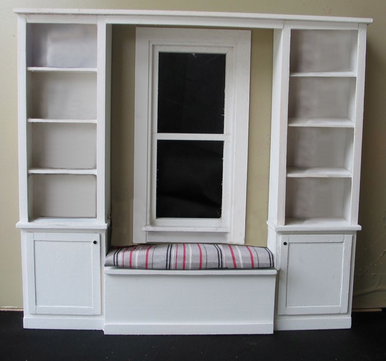
Last year’s N.A.M.E. day project, the alcove (photo from http://name-carmelindiana.blogspot.com/2011/12/name-day-2012-october-6-7.html ) sat on my shelf for quite a while. I could not think what I wanted to do with it.


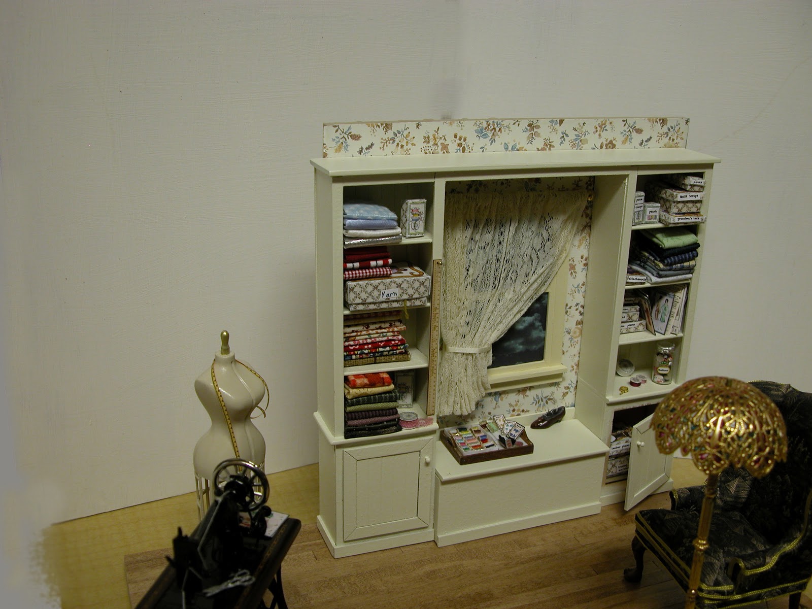
Through a series of events, I decided to use the alcove as part of a sewing room, seen here:


I wired a lamp with one of the nano chips from Evan Design. Its wires are coated with a very tiny insulation colored green and red. The green corresponds to black in DC wiring. I connected the lamp wires to the male end of a pin connector (see below): the red attached to the nano's red wire and black wire attached to the green wire of the nano, so it would eventually fit along the edge of the floor and out a hole in the bottom right back wall.

Next I needed to protect these items inside of a roombox. Time got short, so I did not take pictures as the project proceeded. Later, I deconstructed the roombox to show its parts (see below). However, after securing the box, I painted the inside and then turned it upside down to create a ceiling with holes for lights.

To do this, I cut a piece of white tag board the size of the ceiling and then punched three 1/2" holes in the tag board.

And this is the lovely thing about LED lighting--the diodes can be placed in contact with paper, plastic and other such materials without fear of them catching fire. I made ceiling fixtures from the little 'nubs' that snap plastic strawberry containers closed.

This is not a good photo, but you've all seen the corner of a container. This is a strawberry box with a snap close on each corner. You can only use the top which is rigid. The bottom half of the snap is wimpy.


Cut out the snap and trim it until it is mostly flat, but leave a lip for gluing or taping.

Cut a 1/2" hole in your tagboard (or whatever you are using for ceiling material. This is difficult and you may end up with paper fuzzies inside your circle. I do, so I tack those down using regular hardware store silicone rubber sealant.

 Poke the snap through the hole and either secure it with more silicone or masking tape on the side that will not show.


Now it is time to place the LED as shown in the photo. Secure the LED over the 'fixture' so it will shine through. I used 3 volt LEDs for this project and installed 3 in my sewing room ceiling.
Here is how the underside of the room's ceiling looks with all of the lights in place. You will see that the roombox is upside down and the ceiling is tipped up to show this underside.
Next (below) the ceiling is down and slid into its slot. This picture shows the wires going through the hole in the back top of the roombox.


Below, the roombox is turned right side up and this is how the ceiling looks after three lights were installed.
Lamp wiring

In order to hook up the tiffany lamp, in which I've installed one nano LED, I used a tiny plug, called a pin connector from
Evan Designs. These are tiny 6.7mm connectors. They don't look small because I've taken up a very close-up photo of them. This makes changing lights easy. Simply unplug them.

Below is a picture of the bottom right corner of the bare roombox with the female part (left photo) of the pin connector installed. I've removed the part of the floor that slides in and out for access to wiring. Then I made a tiny hole through the permanent part of the flooring to run wires. This allows me length to "plug in" the lamp when the room is finally all together and yet have the wires remain well hidden behind the right side of the alcove.

Connecting the wires to a battery

Below is a picture of the back of the roombox with all of the red wires PhotoShopped out. You only see the black wires except for the red lead that comes out of the battery holder.

You have three parts to connect: the battery pack black wire (thick wire), the switch black wires, and the black wires of the LEDs.

1. Begin by sliding a shrink tube onto one black switch wire. Hold that black wire with its shrink tube ( the one coming off of the switch) and the three black wires from the ceiling LEDs and the black wire of the lamp's pin connector. 

2. Twist all 5 of these wires together tightly. Or you can solder them together.

3. Slide the shrink tube over this connection so all bared wires are completely covered. Now hold a lit match about 1/2" beneath this connection and watch as the shrink tube snugs down over everything.

4. Slide another shrink tube over the other black switch wire. Hold this remaining black switch wire next to the black lead coming out of the battery and firmly twist the two wires together, or solder them.

5. Then slide the shrink tube in place and snug it down with the heat from a match or candle.

Next come the red wires. Again, I have photoshopped out all of the black wires except the leads from the battery box and the two coming from the switch.


1. Slide a piece of shrink tube over the red lead coming off of the battery holder. 

2. Gather together all of the other red leads and twist them together (or solder them) with the lead from the battery pack.

3. Slide the shrink tube over the twisted connection and use a match or other heat source to snug the tubing down over the connection.

ENJOY YOUR WELL LIT ROOM BOX

Here is my finished room box:


Saturday, December 29, 2012

Part 6 Hiding the Wires


Hiding LEDs in attic and ceiling of main level:

I have wanted to light the interior of the shop and the attic without having obvious lights as the shop is supposed to be a 1920s era building. So I have set up some hidden lights.


These will be 3 volt LEDs (1.8mm), and each will have its own wires running to the power jack. I’ve also sanded the surface of these lights to avoid the spot-light effect.

Since these lights have arrived with 14" wires, I need to add extra wire in order to snake, via hidden pathways, them down to the power jack. To do this, I began underneath the building. I pushed a red and a black wire (from my spools of extra wire) up through the hole at the back (as shown before).

Hiding them presented something of a problem. Most shops I've ever been in have, in some corner, a stack of wood of various sizes. I made a piece for this set of wires out of channel trim. I glued two pieces of channel (looks like a 'u') trim together to form a hollow piece of wood to stand in the back corner.


I ran the wires all the way through this piece up to the edge of the attic, and then I attached the red wire to the red wire of my 1.8mm LED and the same with the black wires. (Am I boring you? Surely most of you could deduce this part, but for the advantage of some who cannot 'see' this, I'm explaining in detail.)

To connect these wires, one could solder them, but I believe they will be secure enough by simply being twisted together. I slid a piece of shrink tube over each, then twisted the LED red to the red from my spool. I did the same with the black wires. I slid the shrink tube over each twisted connection and held this over a candle flame until the tubing had shrunk over the connection making it pretty secure.

I then taped the wires in place, so I could measure the length. I cut the spool wire underneath the building and stripped about 1/3" of the insulation off the end of each wire. [see: Make wires shorter or longer, strip the wire!  http://www.modeltrainsoftware.com/video.html ] 

I tested the connection to make certain that the LED would light. Testing was simple. I held the bare end of the red wire against the positive side of a 3v. battery and the naked end of the black wire against the negative side of the same battery. Yay! That LED lit up.

Next, I put a piece of masking tape on those two wires and marked them as Right Attic and taped them to the bottom of the building. Using Aleene's Tack-it Over & Over (because I want to be able to change these LEDs if one of them should go bad), I glued the wires down along the top edge of the middle rafter and along the attic wall. These wires show, but I intend to paint them tan to blend with the wood and pile some junque in front of the wires to hide them. Every attic has some junk, right?
  
For the second attic light, I bared the ends of the spool-wire, this time before threading them up into the building. I'm learning. I followed the same proceedure. Here, however, I found that my shrink tube connection would end up inside of the channel trim and would not fit. Not wishing to waste the wire, I found a larger piece of channel trim.

In the picture below, you can see that one LED is installed and the second one is at the beginning of being installed. 


Just in case anyone would look in through the attic window, I painted over the wires with white paint. And this next photo shows the black and red wires before they were glued into the larger piece of channel trim.


Below, you can see the underside of the building where the wires to the first attic LED are waiting eventual connection to the power source and on/off switch. You can also see the second attic LED wires in preparation for their being glued down, and marked. 

I tested the new connection and found it worked, so glued and marked the second attic light.
====================================

My next effort will be to provide some indirect light for the main area of the shop. To accomplish this, I have made holes and grooves in the ceiling of the main floor.


Below, you can see the attic-floor/main-room’s ceiling lying on my work table waiting for my order to arrive. I have not yet decided how I will hide the wiring. I want the LEDs and wires to be removable in case the need should arise in the future.


Stay tuned for more.


Wednesday, December 26, 2012

Part 5 Constructing Fixtures - porch light


Constructing Fixtures 2
Making the porch light:

I need a porch light for this building, and I want it to be something like the drawing below. I’ve looked everywhere on the web for lamp parts that can be wired with LEDs and have finally decided that I need to make them myself.


First, I tried a paper cone. This is more difficult that it would seem. No one seems to have a water cooler with those paper cone drinking cups anymore. So I tried to make a paper cone. Each cone I made leaned ever so slightly off center even when drawn with drafting compass and ruler. I also drew the shape on the computer to get it absolutely symmetrical, but it still did not turn out to my liking.


Needless to say, I did not take pictures of these failures.


Next, I bought a ‘yard’ light which turned out to be too large (2 inches in diameter). I thought, oh well, I’ll just make a smaller item of similar shape inside this light. I made one from polyclay but when I baked it, it crumpled a bit and looks more like an old hat than the shade of a fixture.

Now I was frustrated because nothing was coming out like my drawing:

Part numbers in above drawing are JAR-JAF.com parts.

Then I had to stop this project because of the demands of my day job. I also had to go for my annual physical. While there, I asked the nurse if she had anything that looked like a cone and told her why I needed it. “I’ll ask,” she said very generously. When she came back into the room after the doc was finished with me, she gave me the item below:


 Above is the part I was interested in, so I brought it home and began by spraying it with Krylon Fusion, so I
could paint it after cutting it down.

I then drilled a hole in the base of the vial (or as it will 
end up) the top of the fixture shade.

  I've initially fit the parts of this fixture together. The wires run easily through the brass rod, but the 3 volt LED itself and its base connections do not fit well up in the new shade. I need a larger part for concealing the base of the LED, a ceiling plate, a metal top for the shade and paint.

I have ordered these from JAR-JAF.com.
While I wait, I will begin wiring some attic lights which will not have shades as they
will be hidden in the rafters.


I urge you to look at other sources for making fixtures like Kris’s blog

http://1inchminisbykris.blogspot.com/2010/11/november-project-lamp-shade-part-1.html


Stay Tuned... for when I get my order from JAR-JAF


Wow, I totally forgot to come back to this section. Here are photos of the finished porch fixture: 
Ready to be installed

In place but not yet glued as I still needed to check the wiring before gluing when the photo was taken